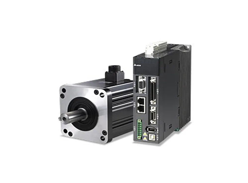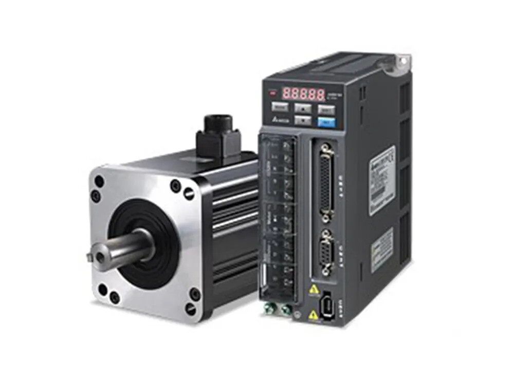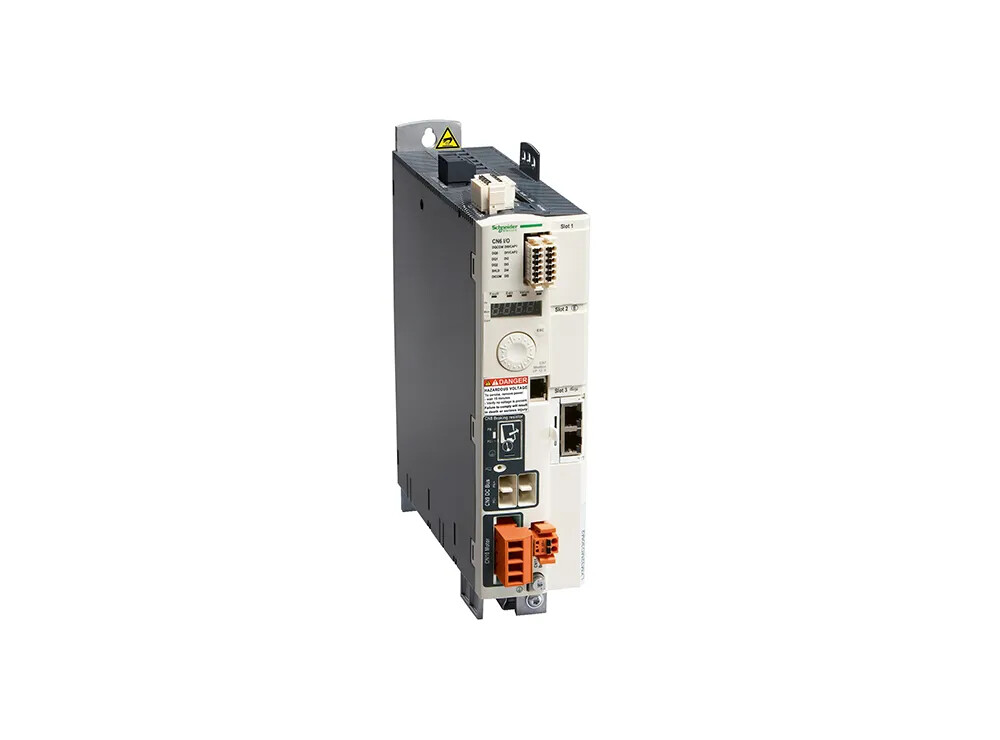

Improving production efficiency and capacity is a crucial goal in modern manufacturing.
Among these, the utilization of servo rotary table workstations plays a significant role in increasing production capacity. This article will go through the design factors for servo rotary tables.
What is a Servo Rotary Table Mechanism, exactly?
Rotary table mechanism design has a wide range of applications and can be found in a variety of industrial mechanical systems.
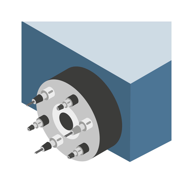
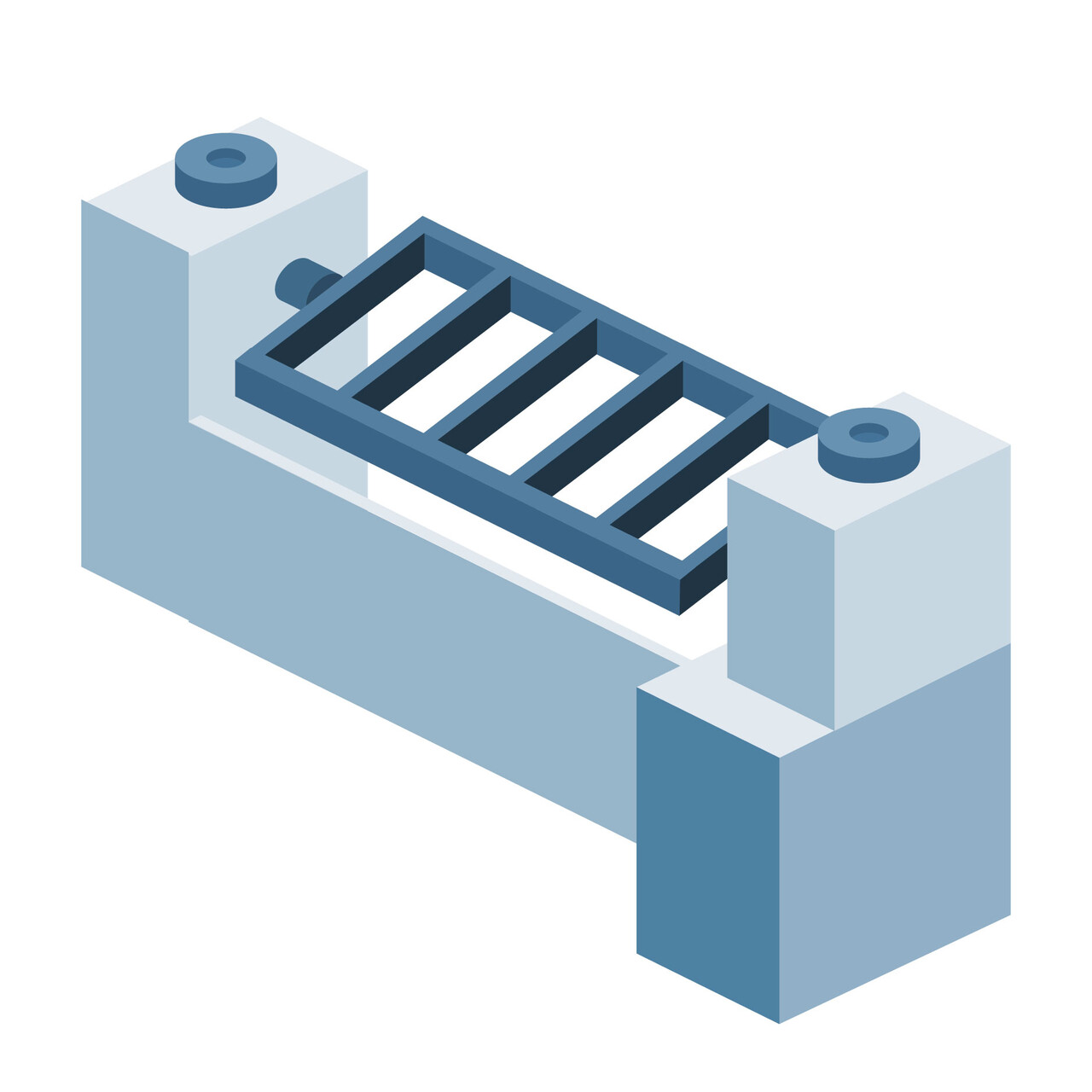
These mechanisms not only improve productivity at work but, with proper design, may transform systems into steady working speeds, achieving speedy and precise angle control. Servo rotary table mechanisms are generally classified as horizontal rotary tables or vertical rotary tables:
Common Rotary Mechanism Designs
Considerations for Servo Rotary Table Design:
Torque Adequacy: Although objects revolving at a steady speed do not require torque, overcoming friction does.
- Torque for acceleration:
- Torque for acceleration (N.m) = Moment of inertia (kg.m^2) x Angular acceleration (Arc/sec^2).
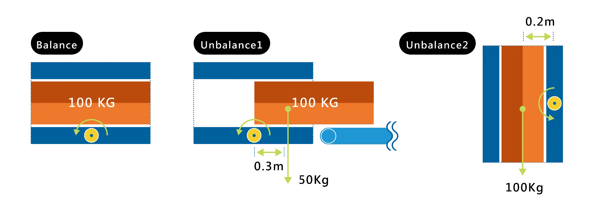
- Unbalanced torque owing to uneven loading should be avoided while using vertical rotary tables.
Appropriateness of Moment of Inertia Ratio
What exactly is Moment of Inertia?
- The ability of an object to keep its initial motion Inertia(An object in motion tends to stay in motion, whereas an object at still tends to stay at still.)
- The ability of an object to maintain its original rotational motion Moment of Inertia (such as a revolving gyroscope or the rotary Earth).
2. Common formulas
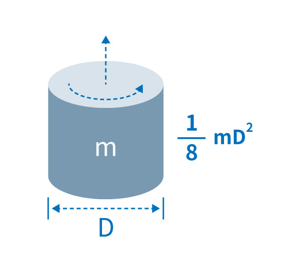
Moment of Inertia of a Cylinder (kg.m^2)
= 1/8 x m(kg) x D^2
where m is the weight of the cylinder (kg) and D is the diameter of the cylinder.
- Moment of Inertia Ratio= Motor Rotor Inertia/Equivalent Load Inertia(Refer to the motor rotor inertia in the motor manual specifications.)
- Note: If the moment of inertia ratio is too high, the servo-controlled rotary table may move around, leaving it unusable owing to poor tuning.
The Savior of High Moment of Inertia Ratio - Reducer
A reducer not only turns high-speed motion into a slower, more suitable motion for certain activities, maintaining consistent speed and avoiding speed faults, but it also effectively distributes force to lighten the stress on mechanical components, extending their lifespan. A servo system's most important job is to greatly lower the square of the moment of inertia ratio.
Common Types of Gear Reducers
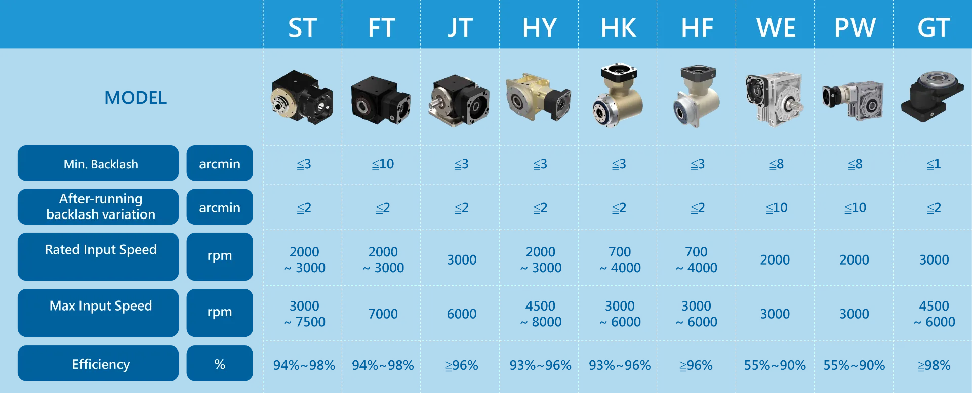
The most common types of gear reducers used in industrial applications include planetary gear reducers, worm gear reducers, helical gear reducers, and harmonic drive gear reducers. When choosing a gear reducer type, you should think about how precise you need it to be, how long it should last, its rated torque, its highest torque, its rated speed, its efficiency, and other factors. Gear reducers from major manufacturers represented by Ace Pillar are tested and can give design reference data to customers.
Mastering Your Reducer: Important Factors to Consider When Choosing a Reducer
An example of a poor decision in servo Motor Selection
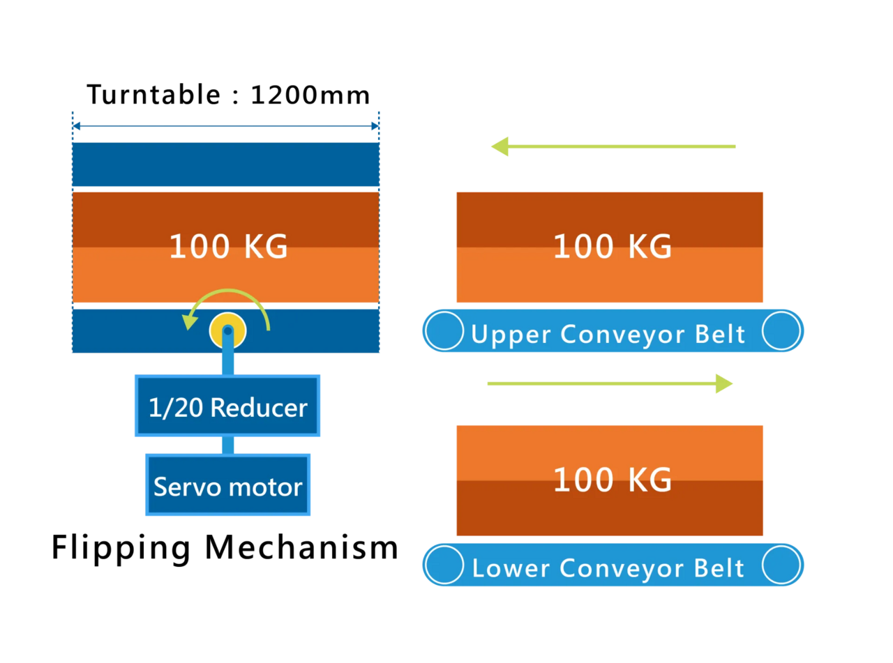
The customer created a flipping mechanism for a conveyor line with a maximum load of 100 kg on the object. Initially, they chose a servo motor called ECMA-E213100SS that had a reduction ratio of 1/20 and an inertia of 1 kW. The technical team at Ace Pillar worked closely with the customer to correct the fault and avoid damages caused by the design error. The following are the updated specifications:
Confirmation of Gravity Torque
Unbalance 1:
50(kg)x9.8(Nt/kg)x0.3(m)=147(Nt.m)
147(Nt.m)/20(ratio)/0.9(Efficiency)=8.16(Nt.m)
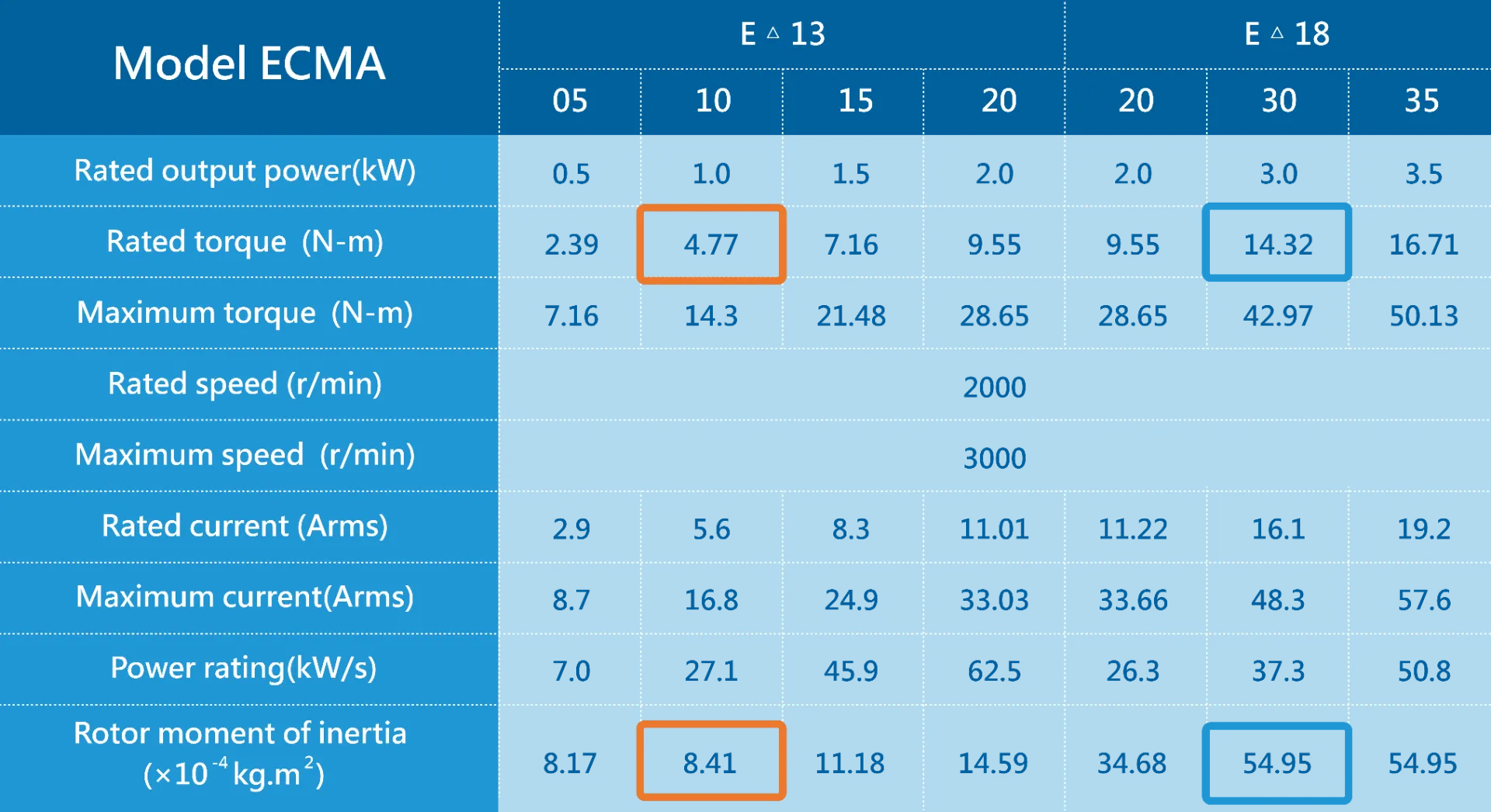
The customer selected E21310 (rated torque 4.77 N.m) with insufficient torque.
Unbalance 2:
100(kg)x9.8(Nt/kg)x0.2(m)=196(Nt.m)
196(Nt.m)/20(ratio)/0.9(Efficiency)=10.88(Nt.m)
The customer selected E21310 (rated torque 4.77 N.m) with insufficient torque.
Confirmation of Moment of Inertia Ratio
1/8 x100(kg) x 1.2(m)^2 = 18(kg.m^2)
18/20(ratio)^2 = 0.045(kg.m^2)
0.045/0.000841 = 53.5 times E21310 poorly tuned
Conclusion: It is recommended to use ECMA-E21830SS + 1/20 gear reducer.
- Maximum gravity load ratio: 10.88 / 14.32 = 76%
- Load moment of inertia ratio: 0.045 / 0.005495 = 8.19 times
FAQ

